Ive decided to build a hydroponics system. I will be building a multi grow system which normally costs about $1500. My system is the EXACT same and costs 3/4 less.
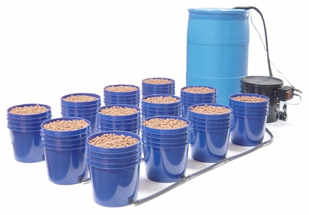
This is an Ebb and Flow type system using 12 buckets, a controller and a reservoir.
The construction of this system will take place over the next week. Pictures will be taken all along the way.
Supplies:1x Diehl Timer. Part Number: TA4079 (Google)
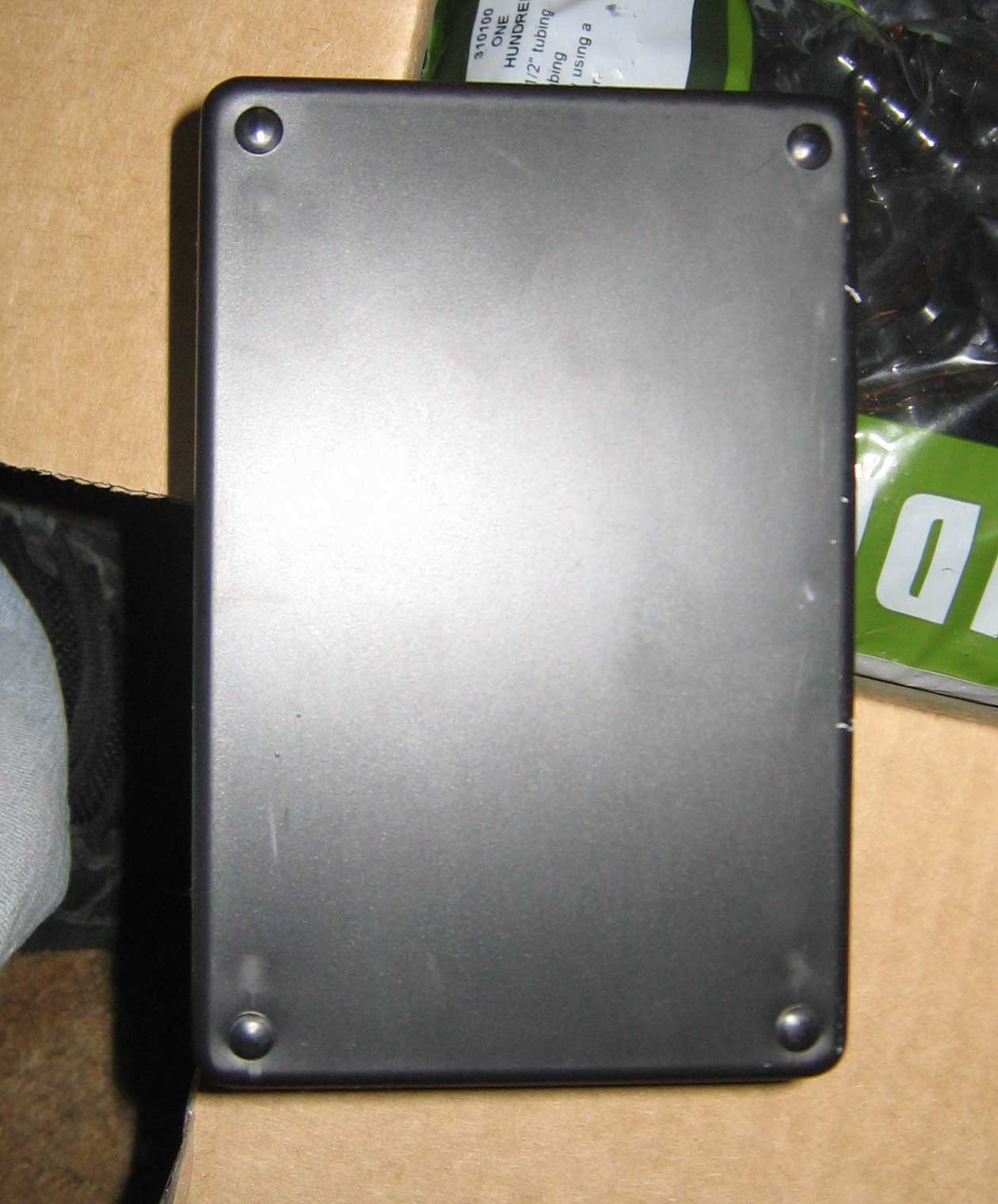
1x Project Enclosure (Radioshack or Lowes)
1x 8" Electrical Cord (Radioshack or Lowes)
2x Single Socket AC Outlet (Radioshack or Lowes)

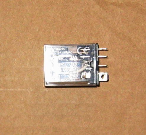
2x 125VAC/10A DPDT Plug-In Relay (Radioshack or Lowes)
1x 55 Gallon Drum (Google)
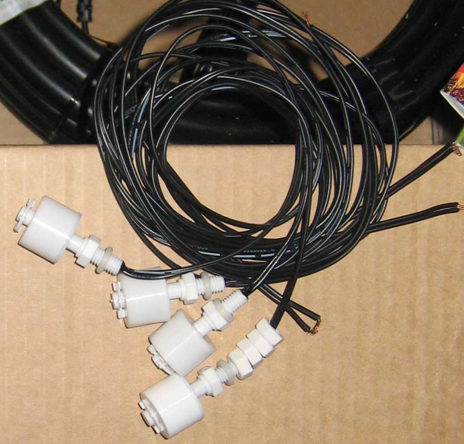
4x Float Switches (Google)
1x 25' Garden Hose
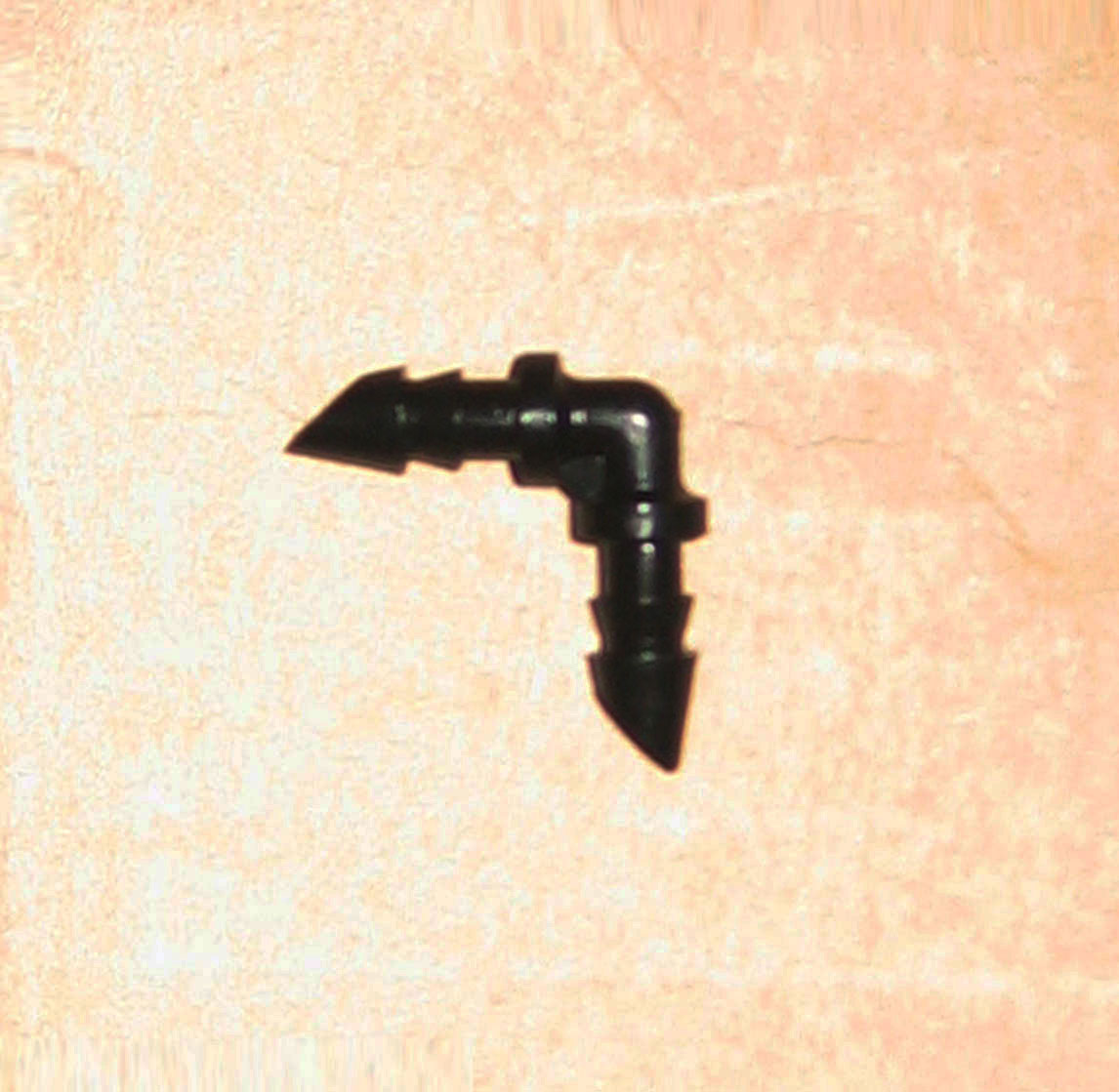
2x 90° Barbs (Wormsway)
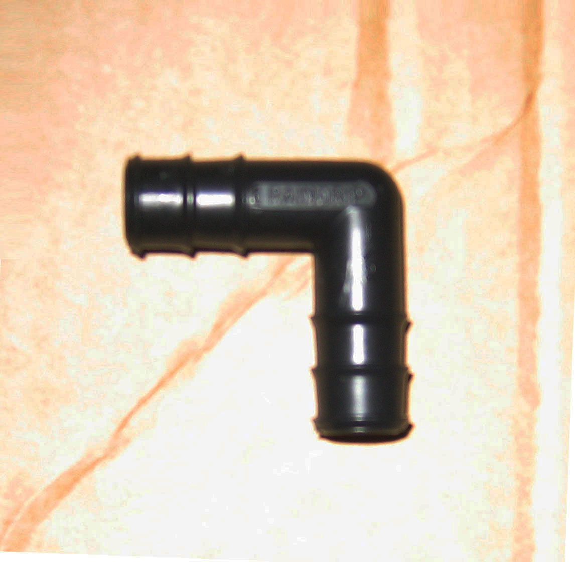
4x 90° Elbow (Wormsway)
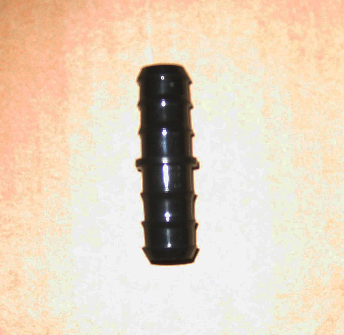
10x 1/2" Straights (Wormsway)
12x 1/2" T's (Wormsway)

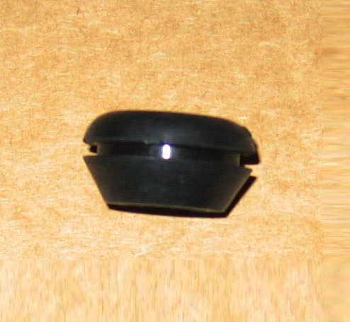
16x 1/2" Grommet's (Wormsway)
12x Grow Buckets
(A lot of people have had problems with their roots clogging their fill/drain hole. Thats because they use 2, 5 gallon buckets. Using 1, 5 gallon and 1, 3.2 gallon bucket there is much more room for healthy roots.
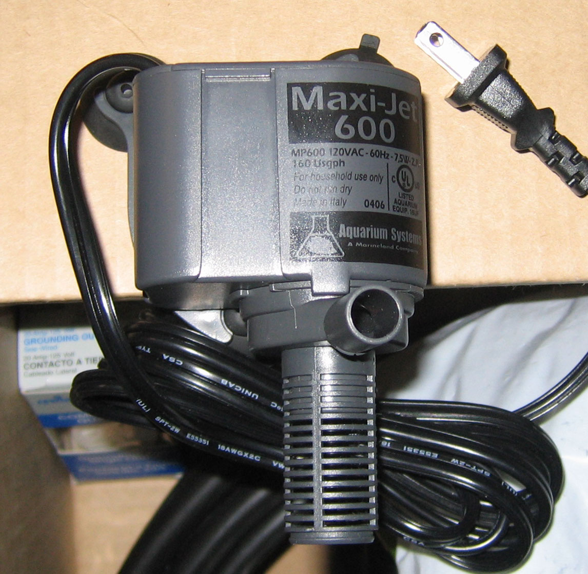
2x Maxi-Jet 600 Aquarium Pump (eBay)
(For larger then a 12 bucket system I would recommend the 900 or 1200)
You will also need things such as:
Wire Nuts
Jumper Wire
Female Connectors
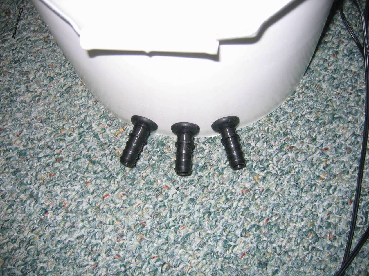
Construction:Glue the float switches to the 90s.
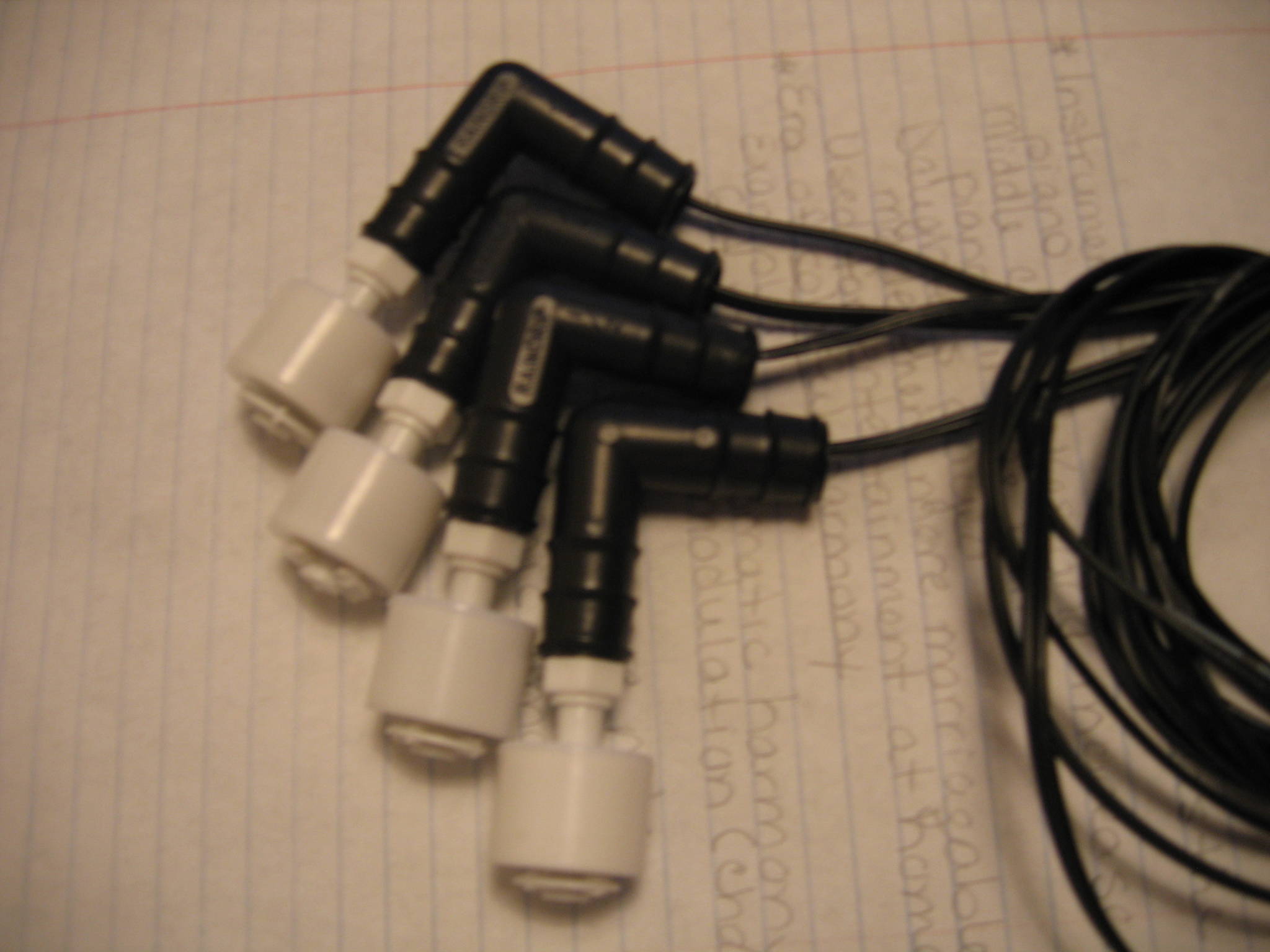
I wrapped 2 rubber band hair ties around the threads. I then put gorilla glue on them and pushed it into the 90. The rubber bands helped to hold it in place while the glue settled.
After about 20 mins of holding the float switch in the 90, I filled the opposite end with gorilla glue and let it dry. Now I have a really really strong hold that should be water proof.
*Careful when using gorilla glue. I got it on my hands thinking it was like super glue... its worse. Water does NOT wash it off, only paint thinner. Gorilla glue also expands so use sparingly.Pots.First I made a template for the 3.2 gal buckets.
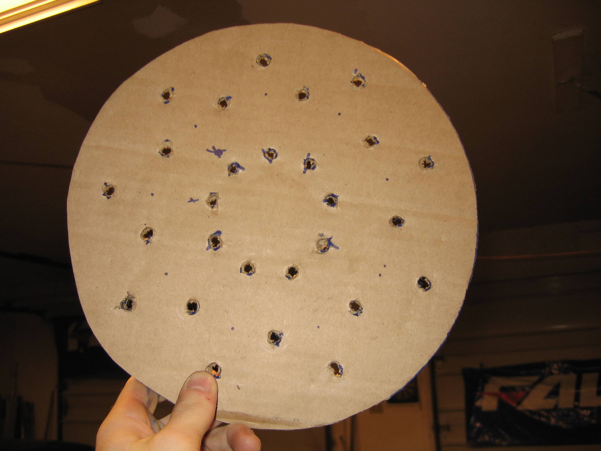
Then I placed it on the bottom of the buckets and drilled. I'm not sure what size bit it was. but it fit nicely in the template.
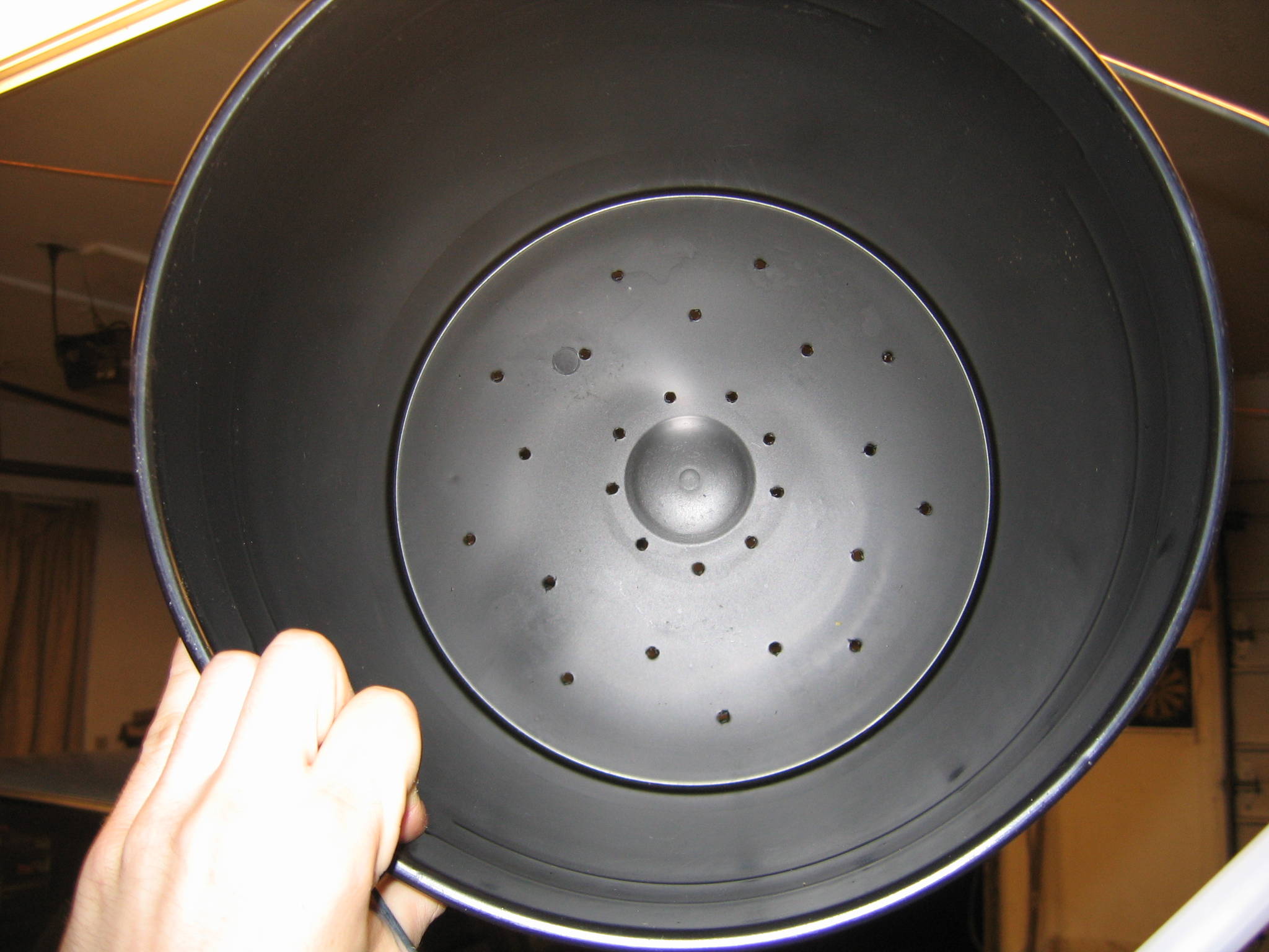
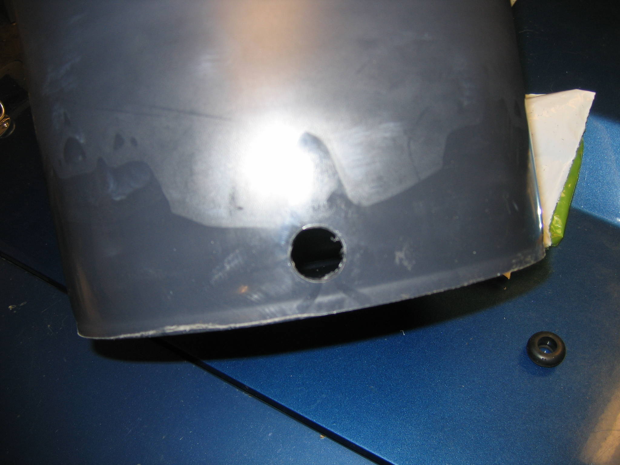
Then I drilled the big buckets that hold the 3.2 gal buckets and added the grommet.
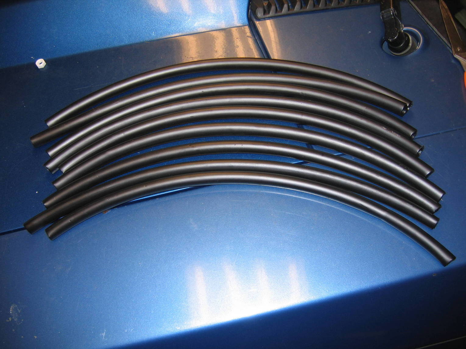
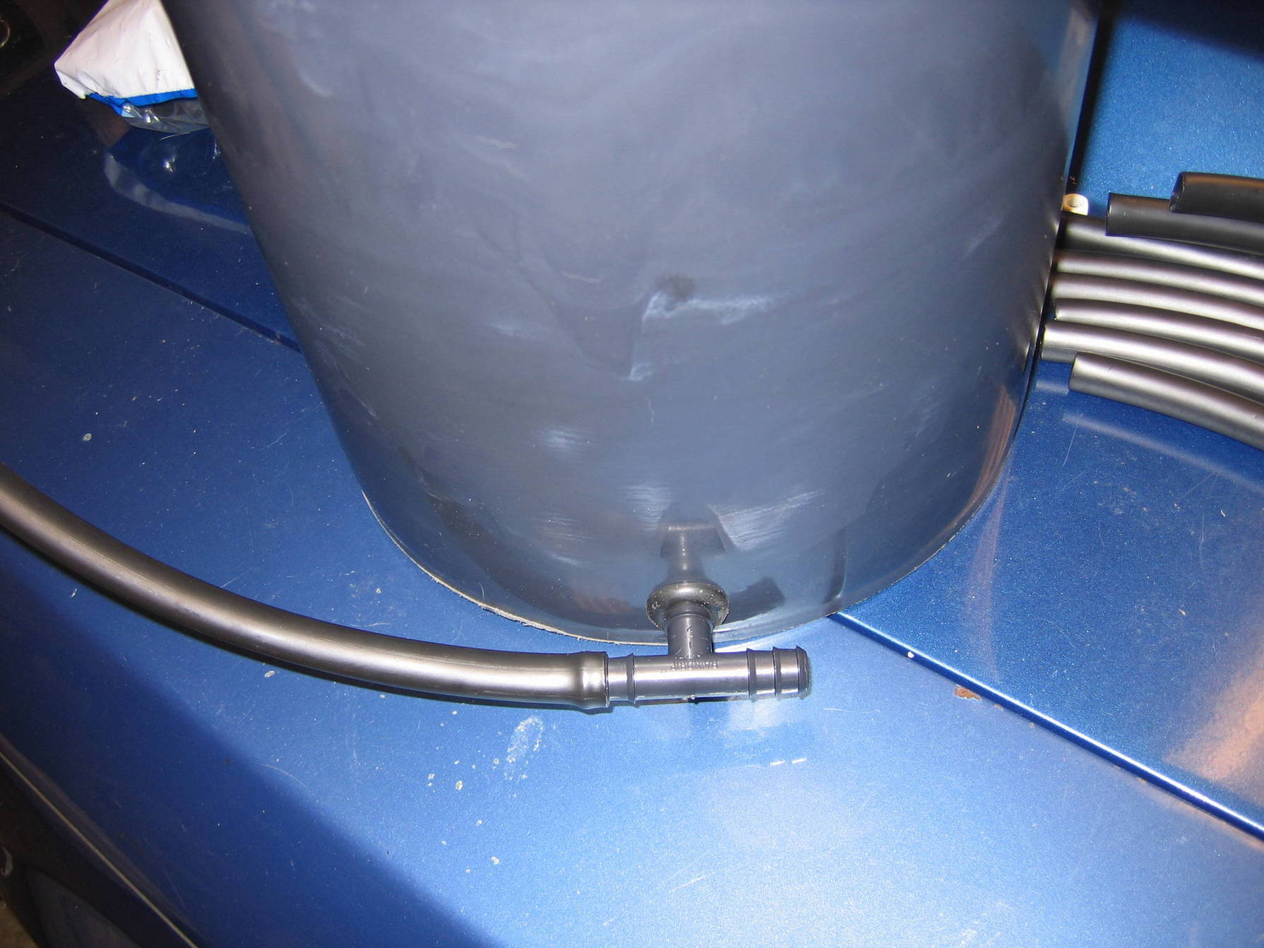
Cut 9 pieces of hose 18" each
Hooked it up. (The hose needs to be on the T more, but I just hooked it up to see if it fit right. Also, push the T in just until it pokes through the other side on the grommet.)
 Controller.
Here is a birds eye view of the controller.
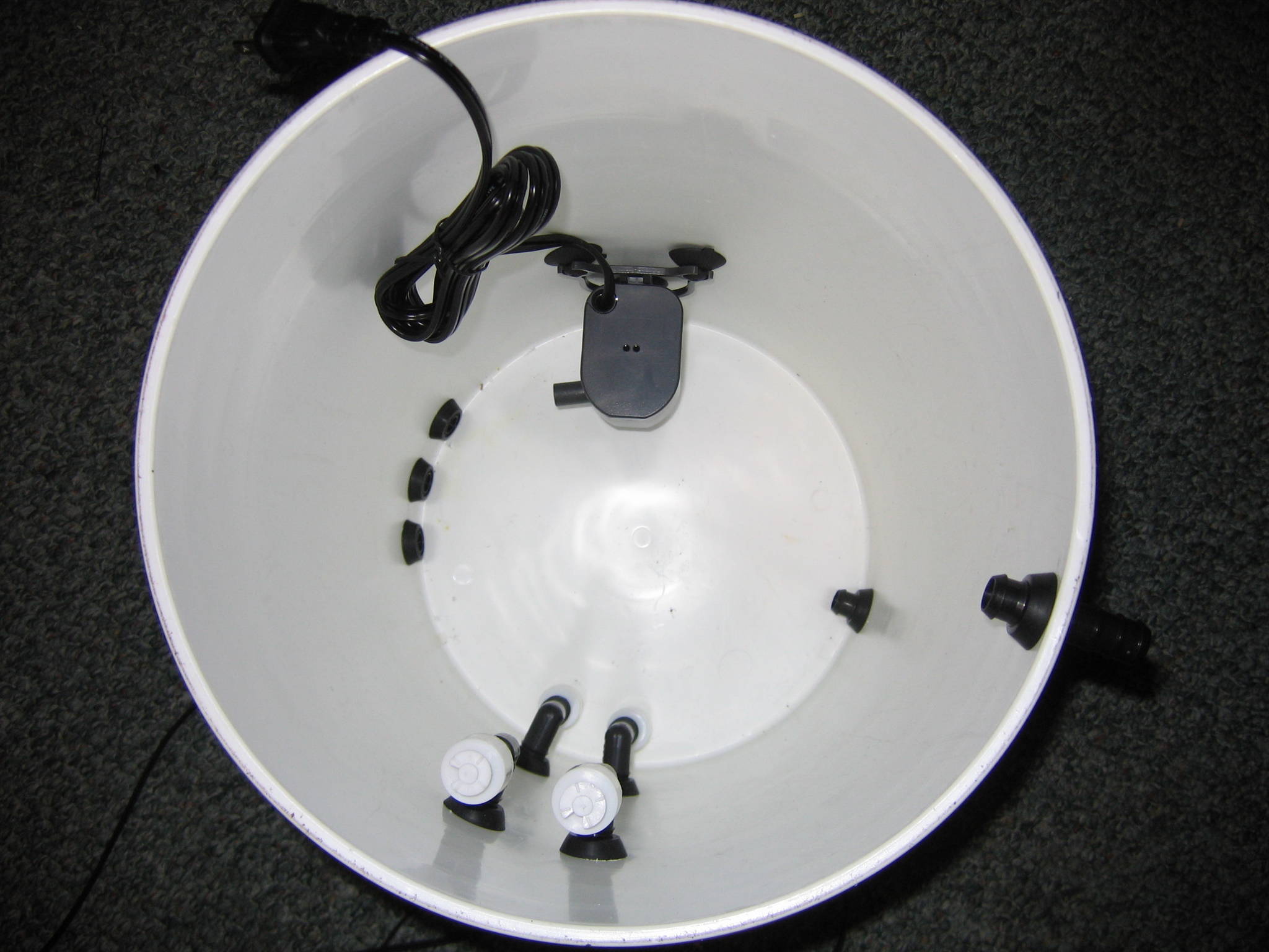
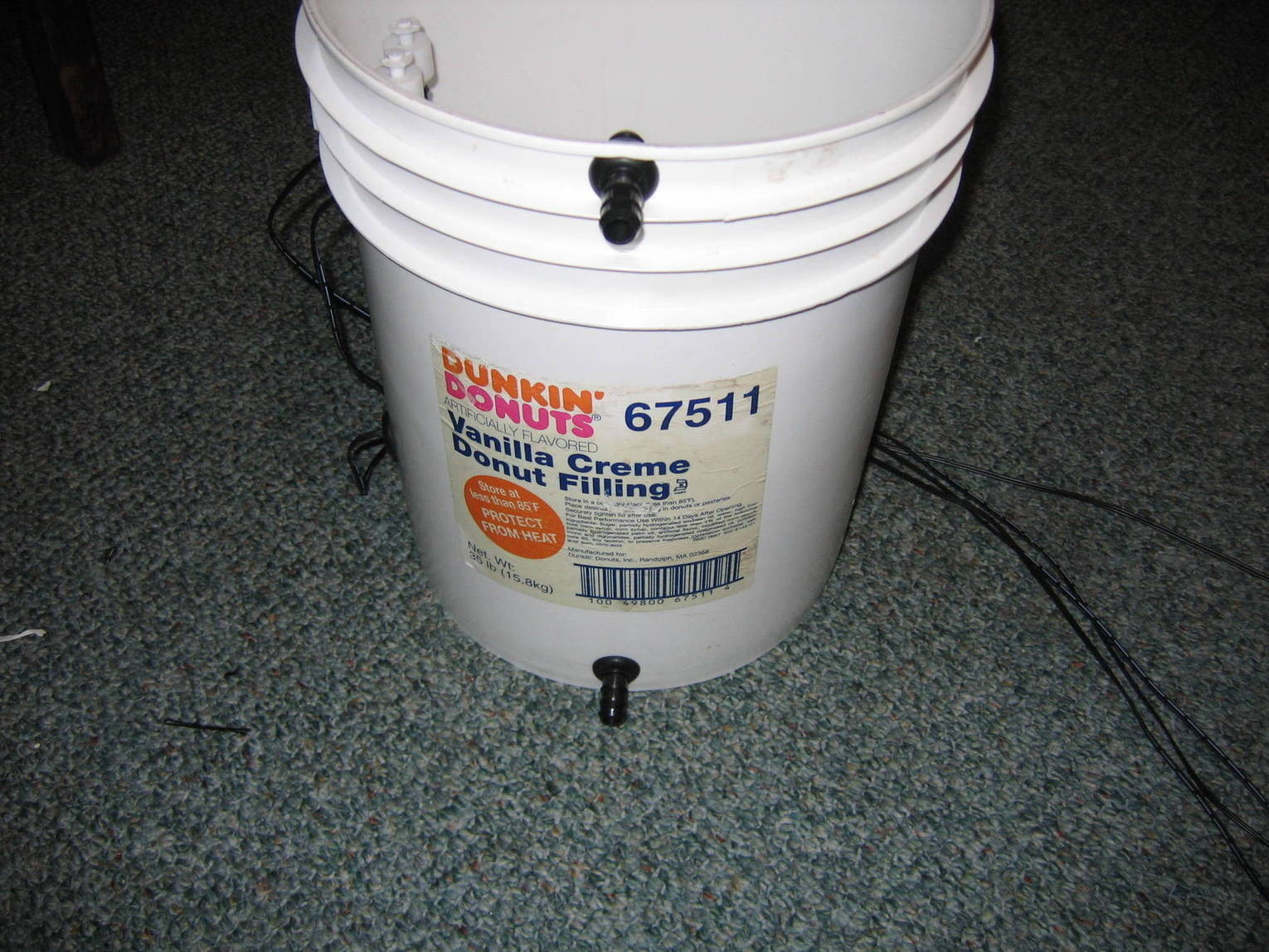
You will want to drill your holes exactly like I have.
These holes are 1.5" apart from one another and 1" from the bottom. These 3 lines are whats used to hook your controller to the 12 pots
Directly opposite of that, is the reservoir water in and reservoir water return. The bottom line is 1" from the bottom and I placed the top one in the center of the top two ribs.
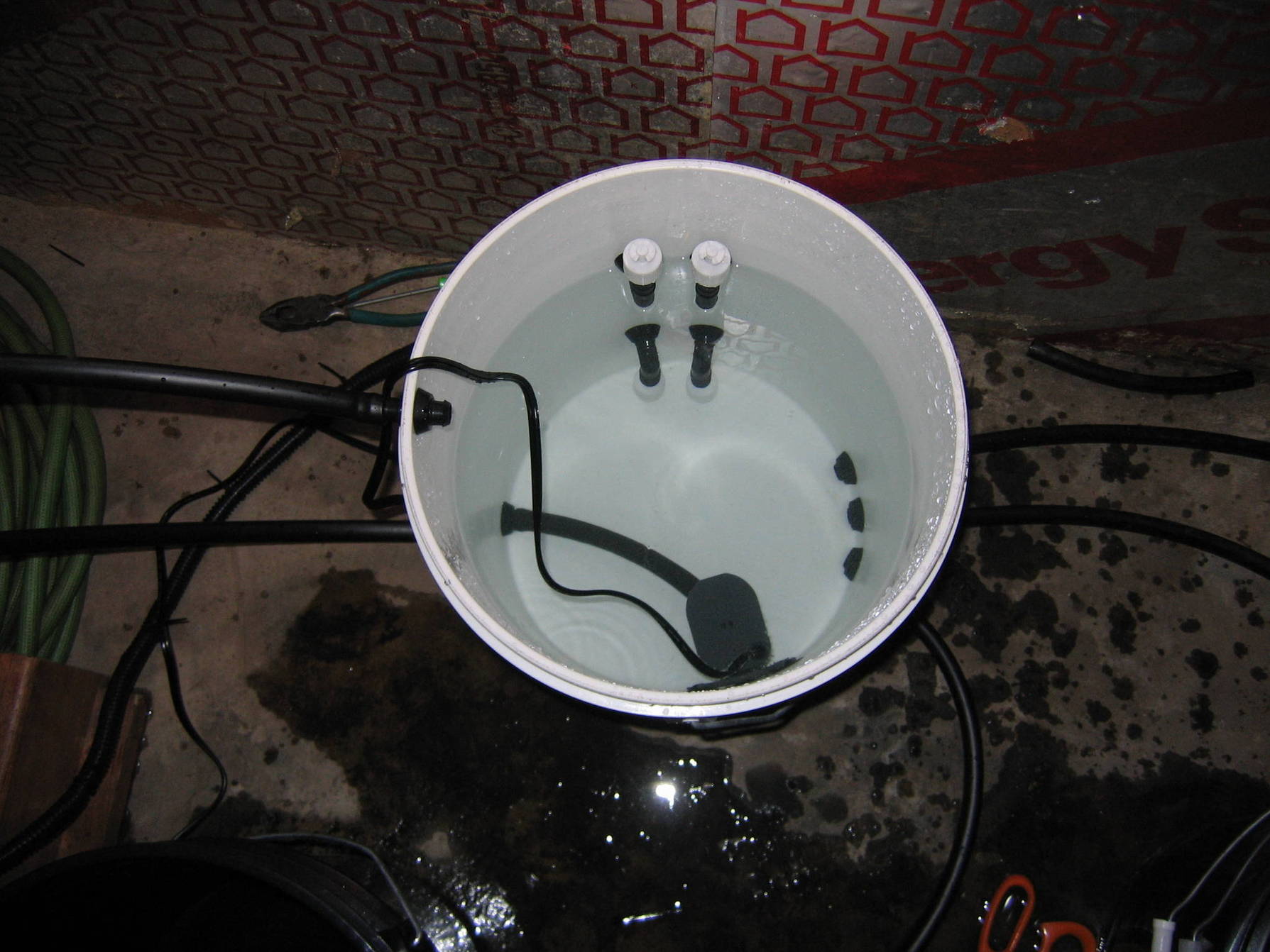
Now in between the first set we drilled and the second set but more towards the second... Drill for the float switch.
The bottom left hole is 3 1/2" from the bottom. The bottom right hole is 3 3/4" from the bottom and 2" to the side of the first hole.
The top two holes are placed directly above the others. You will want to drill your top holes AT LEAST 4" from the top since the float switch 90 = 3" and you want a minimum of 1" at the top where the water wont go.
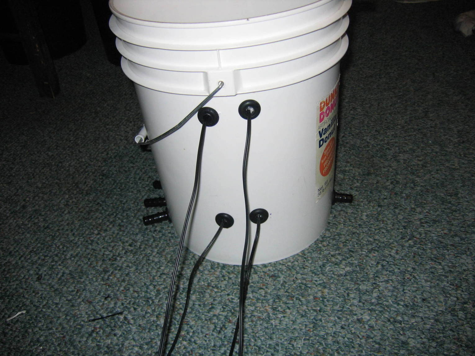
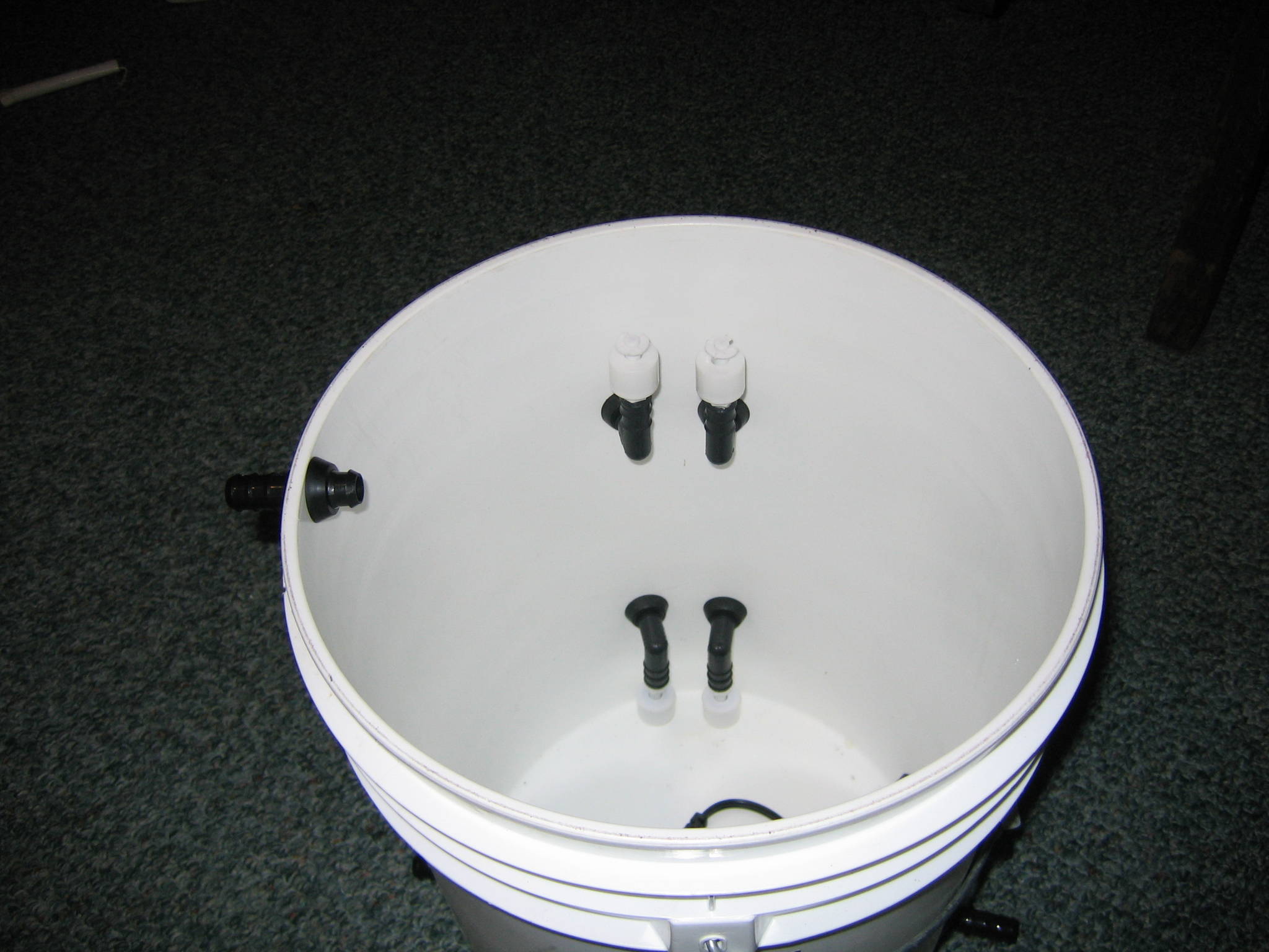
You will want to place the bottom switches facing down and the top switches facing up.
 Controller Box.
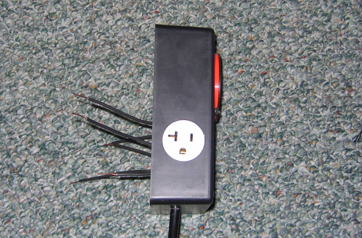
For the controller box I started by measuring the outlet and the timer. Both were the size that I didn't have bits for. So I drilled smaller and used a file to file the holes bigger....
A perfect fit ;)

I temporarily have wire holding the timer in until I can get some screws.
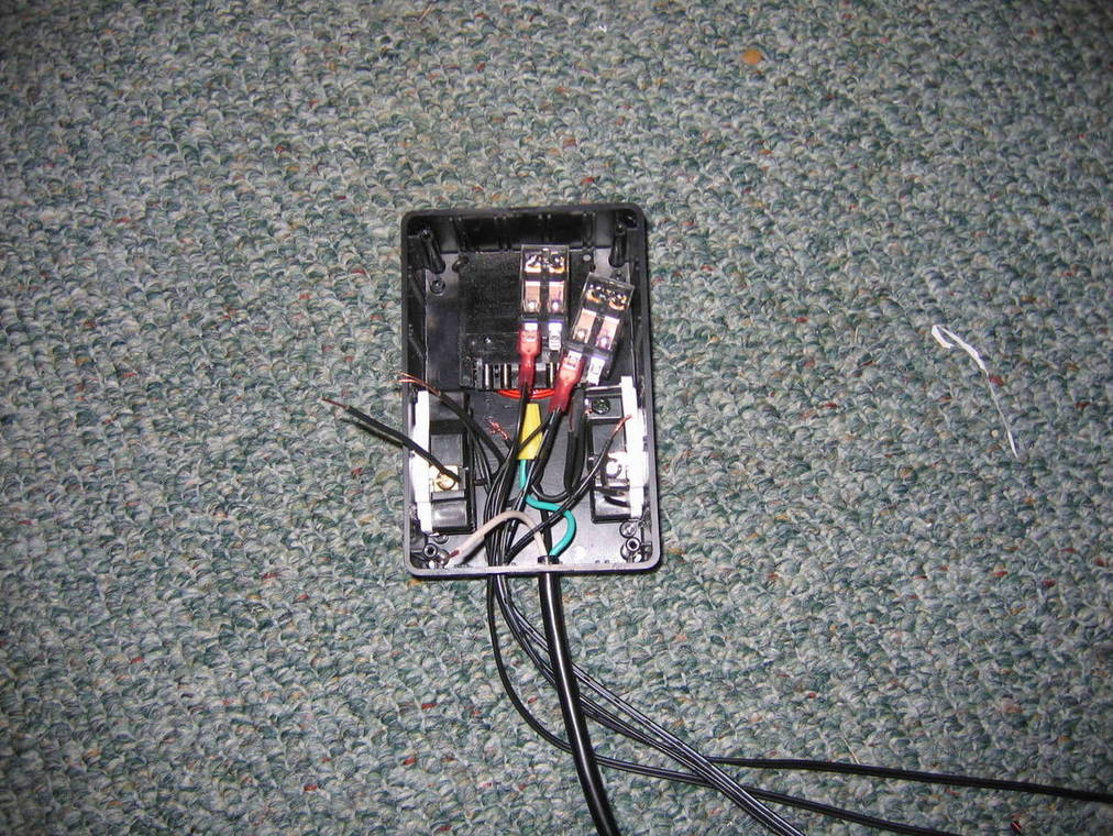
Here is the inside. I should have just enough room for all the wires and the 2 relays.

I also drilled 2 holes on the bottom. One for the electrical cord and one for the controller buckets float switches to go through. Ive decided to do that rather then attach the controller box to the actual bucket. That way its more accessible.
From here feed your float switch wires through the other hole in the bottom of the box.

High Level-High refers to the top switches, highest switch.
High Level-Low refers to the top switches, lowest switch.
Low Level-High refers to the bottom switches, highest switch.
Low Level-Low refers to the bottom switches, lowest switch.
Join your HLH and your HLL switches by connecting one wire from each with a female connector. Attach a female connector to the other wire from the HLH switch. Then connect 2 pieces of wires with female connectors to the other wire from the HLL switch.
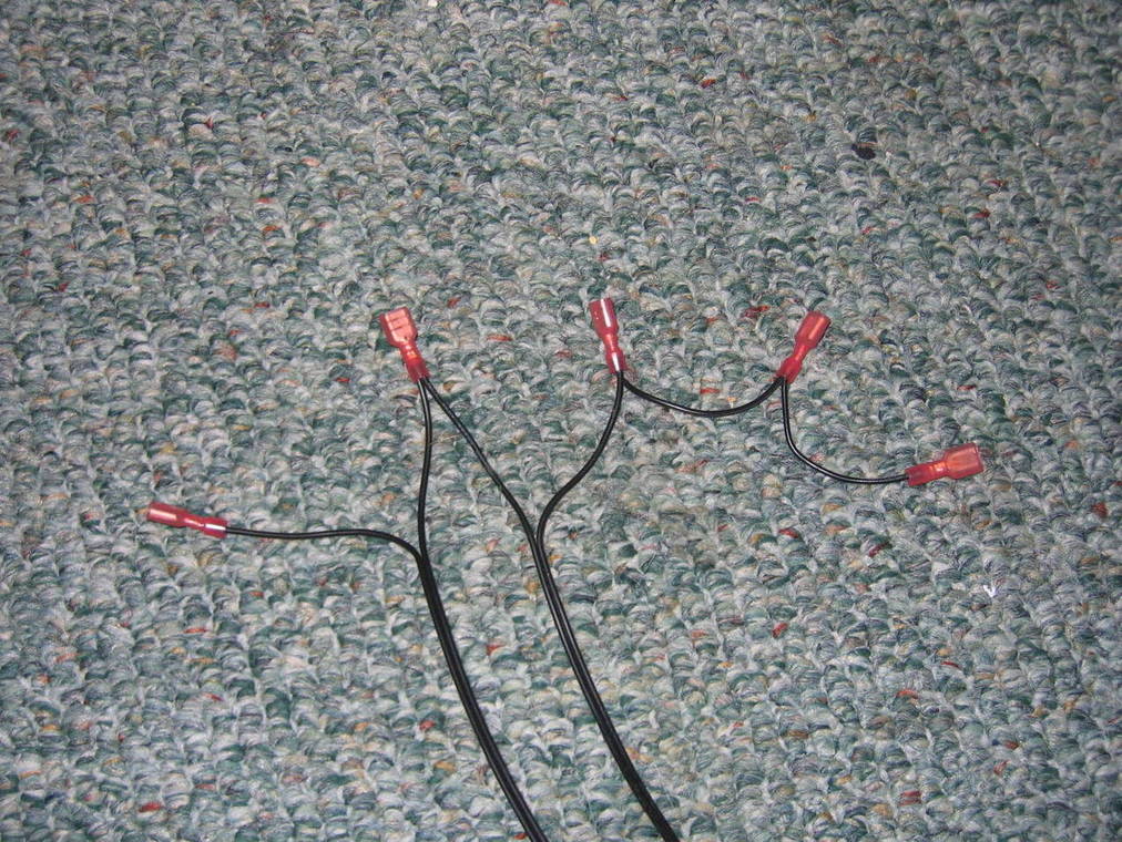
From left to right: HLH HLL
Relay B spot #3. Relay B spot #7. Relay B spot #6. Relay B spot #5. Timer spot #3Join your LLH and your LLL switches by connecting one wire from each with a female connector. Attach a female connector to the other wire from the LLH switch. Then connect 2 pieces of wires with female connectors to the other wire from the LLL switch.
From left to right: LLH LLL
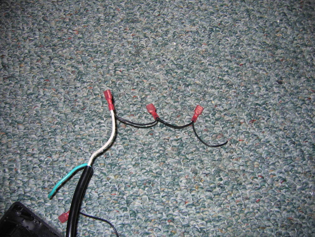
Relay A spot #3. Relay A spot #7. Relay A spot #6. Relay A spot #5. Timer spot #4Take the green wire from the power cord and the green wires from the outlets and wire nut them together.
Now you are here.
Take the black wire from the power cord and attach one wire with a female connector. Attach another female connector to the end of the wire.

Now connect those to
Timer spot #1 and #5Take the white wire from the power cord and attach 3 wires using 3 female connectors leave the last one without a female connector.
Connect those to
Timer spot #2. Relay A spot #8. Relay B spot #8. Wire nut the one without a female end to the white wires on the outlets.
Now connect a female connector to each of the black wires on the outlets. Connect one to
Relay A spot #4. and the other to
Relay B spot #4The controller is complete.
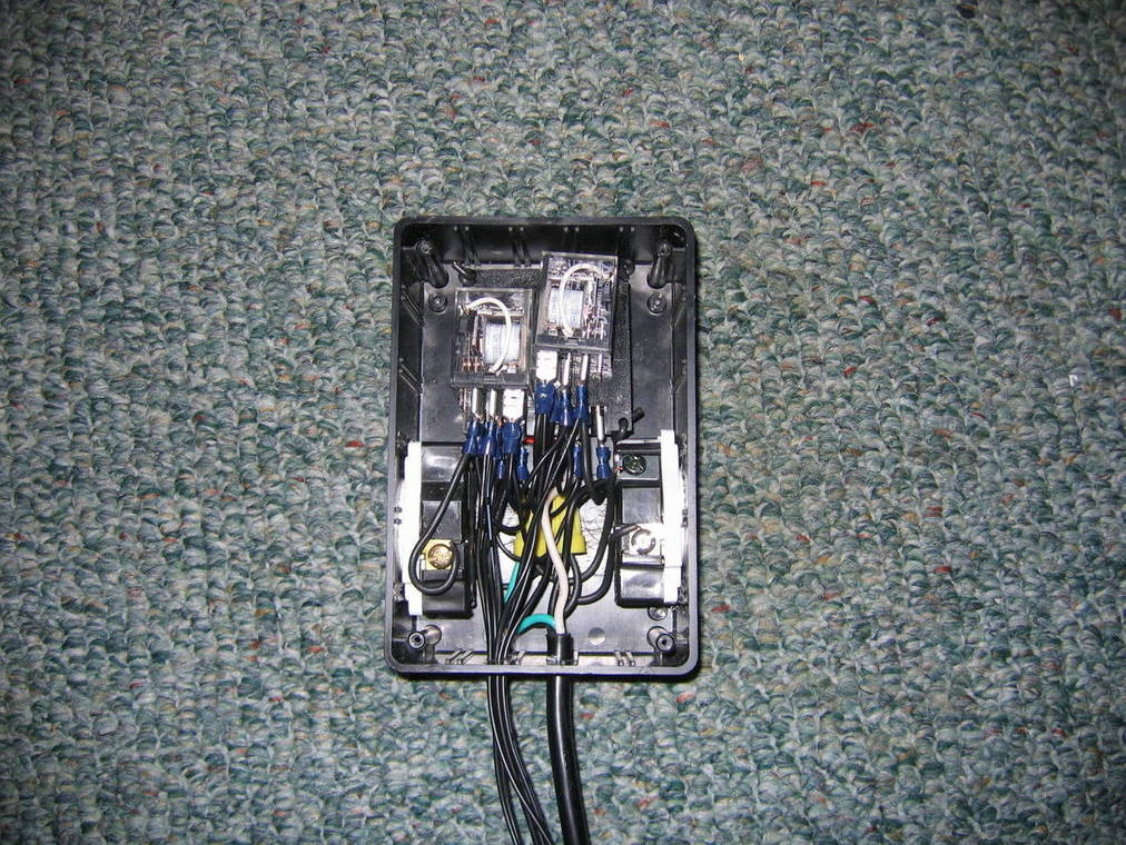
*I had to switch the female ends in the previous picture with these ones because the red ones had a too small of a hole and the wires kept coming out.The End Result.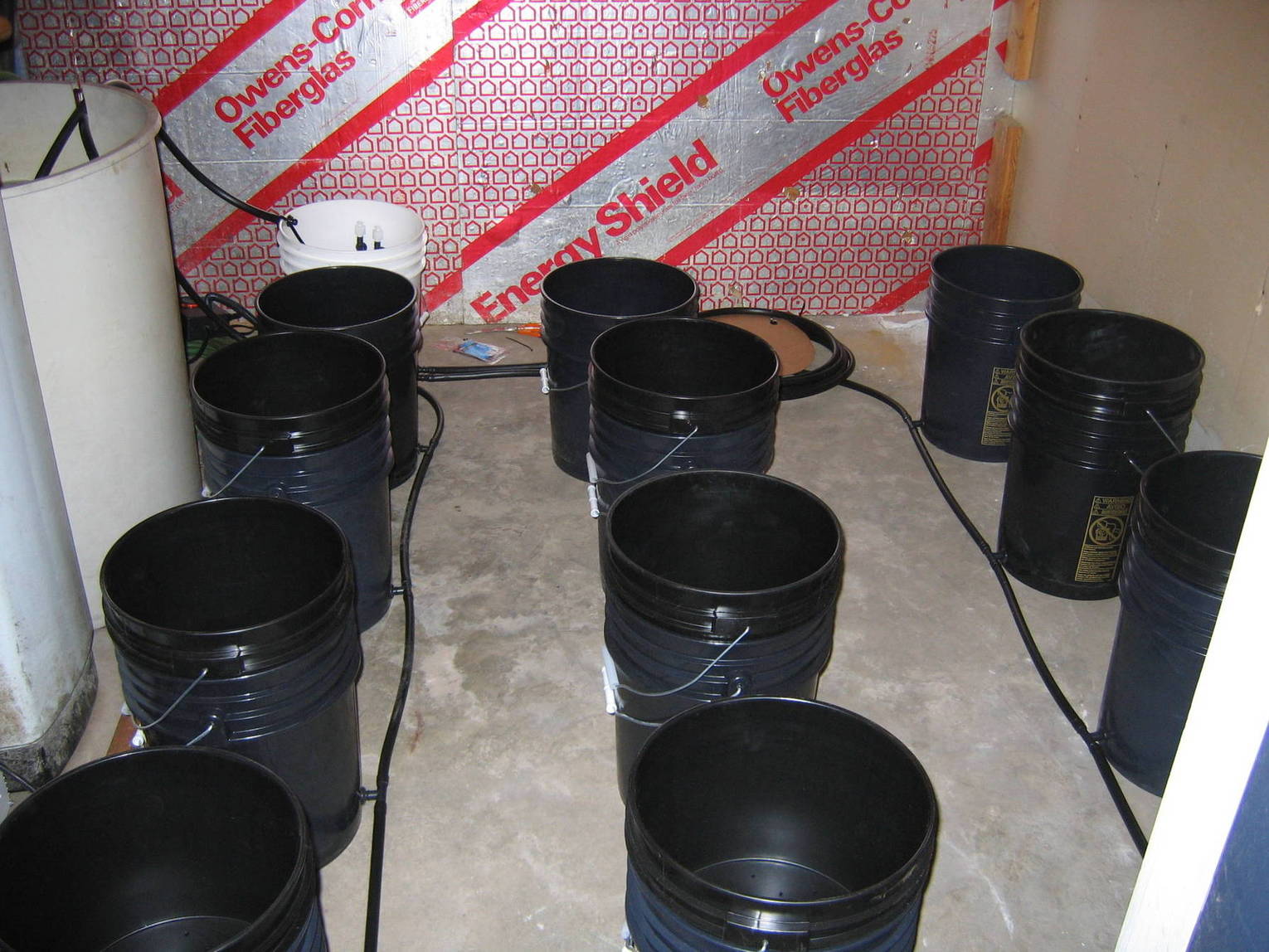

When I ran the test earlier, it filled but did not drain. I rewired the controller box 3 times and screwed everything up. After ruining all of my nice covered female connectors, I rewired it and gave it another test.
It still didn't work.
I switched the floats around on the bottom float switches. Still didn't work right. Switched the floats around on the top switched. Now it worked but it was backwards. I then switched the outlets that I had the pumps plugged into. This finally corrected all the problems.
Explanation of whats happening.Timer turns onPower is now on pin 3 of timer..which is connected to pin 6 of Relay B
When the relay is on..6 & 4 make and the pump is powered..
Relay comes on because the High Low Level (HLL) switch also powered by the timer is made..(bucket is empty)..and powers pin 7(coil)
At the same time a holding circuit is created by timer power on pin 5 making with pin 3 through the (HLH) switch to the relay coil pin 7.
This means now you can open the HLL now because the HLH now has control of the relay and now powers pin 7
Water fillsBuckets fill until it trips the HLH. Contacts open and pin 7 loses power. The relay shuts off, and pump stops filling
(Here is why two switches) now say the water level drops a bit and timer is still on.
the pump would surge on and off each time the HLH bobbed just a little.
With this circuit, for the pump to come back on, the water has to drop below the HLL before the pump will come back on.
This spacing between the two switches creates a hysteresis
The HLH can bob all it wants, it has no power once the relay went off because 3 & 5 opened. The HLL has to start the holding circuit again to get HLH power.
If you have ever used a large power tool or machinery that has a separate "Start" & "Stop" buttons..it's the same thing.
Once you hit "stop" it won't start again no matter how many times you push "stop" and vice-verse. Start starts, Stop stops
Basically the HLL is the Start Button, HLH is the stop.
Timer turns offPower now on pin 4 of timer. Switches LLH & LLL are made because they are upside down and floating (away from the C clip) Bucket is full
Relay A turns on, 6 & 4 make drain pump power, and 3 & 5 make
and same holding circuit created on Relay A as on B. LLH is the start, LLL is the Stop.
Bucket is emptyNow power will remain on the Drain circuit as long as the timer is off.
So if the buckets are slow to drain and fills the control bucket till it reaches the LLH trip point again..the drain pump will cycle back on
and run till the LLL shuts it off again. Automatically keeping the system drained.
I've been working on this since around 1PM and now its 7AM. I will run a few more tests when I wake up. Ive having a drain/fill problem. Nothing major, I think its due to the hose I got. It's not flexible at all and I think thats creating a kink in the systems ability to fill and drain evenly.
Oh yeah...I got water everywhere too. If your system isn't working... FLIP YOUR FLOATS FIRST! haha
I had to use a 76 gallon res instead of a 55 gallon. The 76 gallons holds just the right amount.
Both the reservoir pump and the controller pump hoses need to have a small hole put in them and the small 90° barbs inserted. Do this on the hoses right before the leave the reservoir.
*This is so the hoses do not siphon the water out of the reservoir and controller.

