Welcome to the Growery Message Board! You are experiencing a small sample of what the site has to offer. Please login or register to post messages and view our exclusive members-only content. You'll gain access to additional forums, file attachments, board customizations, encrypted private messages, and much more!
|
 Some of these posts are very old and might contain outdated information. You may wish to search for newer posts instead. Some of these posts are very old and might contain outdated information. You may wish to search for newer posts instead.
|
 GROWEED GROWEED
Crack Smokin' Hoe-bags


Registered: 05/03/08
Posts: 826
Loc: []v[] i C H I G A []\[]
Last seen: 13 years, 7 months
|
 GROWEED FINDS: D.I.Y Low bay into a remote ballast growlight/D.I.Y Envirolight Reflector GROWEED FINDS: D.I.Y Low bay into a remote ballast growlight/D.I.Y Envirolight Reflector 
#37603 - 05/22/08 11:54 PM (18 years, 2 months ago) |
|
|
TAGS: Growroom Designs & Equipment, D.I.Y, Lighting, Reflectors
Quote:
Hi there people....Ive been promising to do this thread for almost a year now....
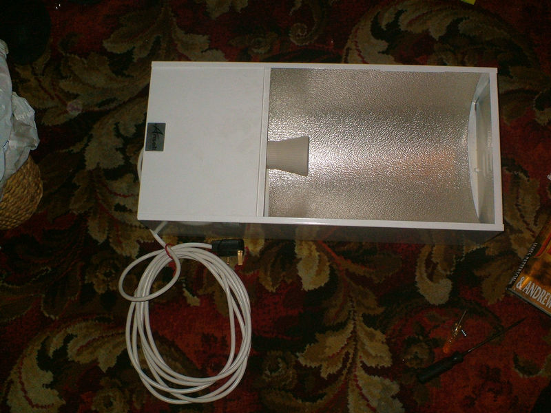
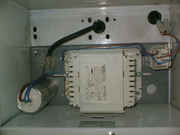
OK, 1st off, ill show you the lamp in its raw state...
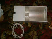
this is what is known as a LOW BAY fitting, commonly used in factories....my uncle uses one in his big workshop, It is perfectly fine to use this type of light as is, and it will grow the same great buds, but it is a little heavy and requires heavy duty hanging to match-so adjusting the height is a PITA, doing this conversion will make it as easy to use as a store bought light..
you will get a 400watt like this in HPS/Mercury(although why you would buy that is beyond me) and metal halide versions for about 50-65 pounds.....cheaper if you look around or have a trade card for one of the trade places! The purpose of this thread is to show you how to make a grow light from this, that is almost 100% recycled from the low bay.
As well as the low bay, for the ballast part of the light you will need 1 x strip connector(2 conn piece), 2 x compression glands, 4Meters of 3 core, 1 x Male IEC connector and 1 x 3 pin plug.
So 1st you need to break it down to its constituent parts... remove the cover on the ballast end and take the power cord off by unscrewing the screws on the strip connector(3 conn piece). Next is the ceramic lamp holder, unscrew the bolts that secure it to the housing, you might find this easier to use pliers or a spanner(wrench for US) to hold the nut on the other side while you turn the screw! Once its off, remove the wires from it by unscrewing the brass screws on the connection point at the bottom of the lamp holder.
Now the Power cord and connection to the lamp holder are removed, you remove the specular aluminium insert from the reflector end(this could take a bit of twisting gently being careful not to bend or fold it)and put it somewhere it wont get damaged-you'll be needing it later! now all that remains is to just unscrew the bolts that are holding the gear tray(the metal sheet that all the ballast components are bolted to), and remove the whole thing in one piece from the housing and put it aside somewhere safe. By removing the tray with all the components still attached, you have less chance of accidentally pulling wires out and having to find a wiring diagram lol. There is no need to replace the wring on the parts, provided it all looks good and the connections are sound, if it ain't broke,don't fix it as they say.
Now comes the part that some of you may find difficult as you need access to an angle grinder, or some means of cutting the Powder coated aluminium housing in two. I did it with my uncle (or should I say i took it to him and he cut it) who has shit loads of tools and is happy to do things like this and get a nice a spliff or 3 for his trouble(after handling the dangerous tools of course) anyway I forgot my cam when i went to cut it so I ain't got a pic of that process, basically lots of sparks((hot metal splinters!!!)) flying and noise, so ear protectors and like good old Norm says, "don't forget to wear your safety glasses", i don't want any blinded ICers on my conscience please. like I said, no pic of what it looks like, but ill do my best to describe it. You want to make the cut, on the inside of the reflector end, just before the bit that the lamp holder was attached to, leaving the Box part intact completely with all its sides, if you cut it right it wont be a problem, so basically you are cutting the ballast box part from the reflector part. mark the line about 1CM from the edge of the box part-this will leave a little foot on three sides so it isn't standing on the flat bottom directly. Use the grinder or saw to cut the box part off, and then make sure you get all the burrs and sharp edges off it with a file,I don't want any ICers bleeding to death on my conscience either!
Now you should have a nice white metal box and a piece of spare scrap metal....
So, you can see where I'm going with this right...the box that housed the ballast when it was a Low bay is perfect to be the ballast housing now and saves you either trying to find/make one, or having to leave the ballast un-enclosed,which is very dangerous IMO in a humid growing environment.
Now, you are ready to start putting your remote ballast together...the 1st job is to fit the 2 x compression glands to the box...as luck would have it, the Low bays I get from a local place already have 2 x 20mm holes cut ready to receive compression glands so thats one less job for me... I guess a lot of them will be made ready to put the glands on... If you haven't ever fitted a compression gland before, its really easy..the round end is outside and the flat end inside, you take off the locking nut from the flat end, and push the bare end through the hole from the outside, then put the locking nut back on and tighten up. a compression gland works by means of a ring of rubber inside a plastic housing, when you screw the round ended nut on it when the cable is in place, the housing squashes the rubber ring and holds the cable in position, compressing more as you tighten the nut on the end. I shall take a pic of this and add it to this thread later...
anyway, once you have fitted both of the compression glands,you are ready to replace the gear tray into the metal box, just bolt it back on to the inside in its original position.
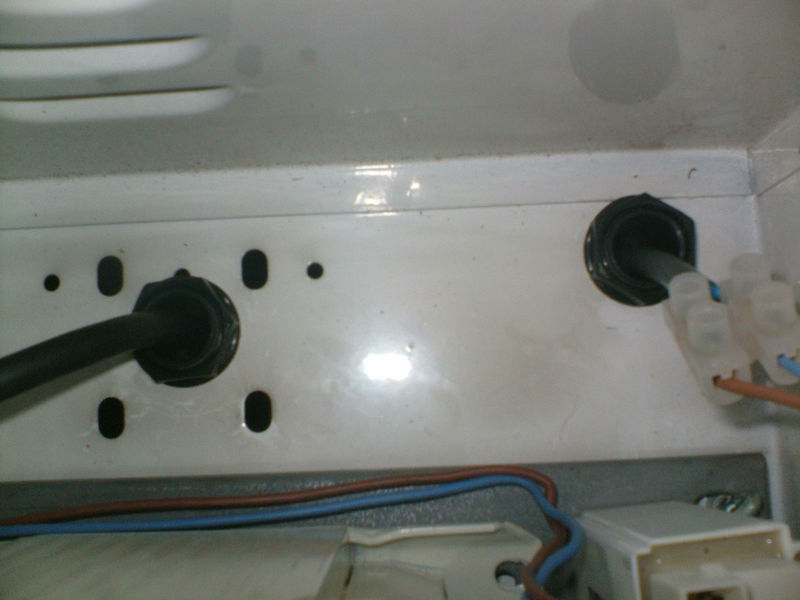
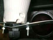
Next you will fit the power cord by removing the round nut from the compression gland nearest the power end of the ballast, feed it through the hole - you only want enough to reach the strip connector and it not be dead tight, don't coil it up inside!! simply screw it back into the strip connector following the markings for the correct wires. repeat the process for the other compression gland with the 12 inch piece of 3 Core cable, except you need to cut a piece of strip connector 3 conns long and use it to connect the 3 Core to the thin solid copper wires coming from the igniter (the white plastic thing that looks like a 9volt battery), there is no earth coming from the igniter, I cut the earth part off this end of the 3 core, and cover the exposed part with electricians tape the correct colour ((green/green and yellow stripes)) I checked this out with an electrician friend of mine and he says it is perfectly safe as it is earthed through the plug! this connection should look like this
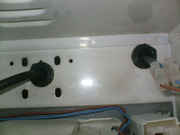
the one on the right.. LOL, finally another pic, i bet u thought this was the worst instructional thread ever, with no pics and my shitty descriptive capabilities lol....
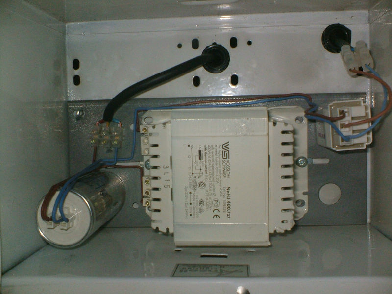
If you have managed to follow me so far WELL DONE lol, but seriously, you should be looking at something like this now
Next up, you take the male (?? actually they confuse me coz the one I call male which you shove in the other, has the holes in it for the prongs which are on the other half of the fitting which i call the female... but if you go by the prongs and holes, then the one you shove in would be female and the one that gets shoved into would be the male..very confusing, i mean the situation not what i just said  and I cant get a sensible word from any1 about it lol) anyway its the one i call the male, which gets shoved into the other one on the end of the reflector cable... (enlarge the 1st of the next pics and you will see it... ) the Fittings are IEC or "Kettle" connections and you will get them at an electrical suppliers and definitely at the growshop and better hardware shops. they are simple to fit, just take the cover off the fitting, put the cable through the rubber sleeve and the little screw down thing that holds it in place, and put the wires though/around the contacts and screw the brass screws in tight...make sure all your connections are clean and tidy, and there are no stray strands of copper inside the fitting loose that could make a connection that you don't want...say crossing the live and neutral which would be bad. and I cant get a sensible word from any1 about it lol) anyway its the one i call the male, which gets shoved into the other one on the end of the reflector cable... (enlarge the 1st of the next pics and you will see it... ) the Fittings are IEC or "Kettle" connections and you will get them at an electrical suppliers and definitely at the growshop and better hardware shops. they are simple to fit, just take the cover off the fitting, put the cable through the rubber sleeve and the little screw down thing that holds it in place, and put the wires though/around the contacts and screw the brass screws in tight...make sure all your connections are clean and tidy, and there are no stray strands of copper inside the fitting loose that could make a connection that you don't want...say crossing the live and neutral which would be bad.
All that you have to do now, is to fit a plug on the end of the power cord if you haven't already, and put the cover back on the front of the box and you have done it. Congratulations, you just built a remote ballast .
Now its time to move on to the reflector... PLEASE NOTE, IN THESE PICS IT IS SHOWN WITH A 3 PIN PLUG ON THE POWER CORD - THIS IS ONE i MADE FOR AN ENVIROLIGHT BUT THE BASIC CONSTRUCTION IS THE SAME, JUST USE AN IEC CONNECTION FOR THIS ONE...I WILL CHANGE THIS AND REPLACE THE PICS WHEN I MAKE ANOTHER REFLECTOR IN A COUPLE OF WEEKS..I ACTUALLY BOUGHT A CMEMORY REFLECTOR FOR THE ABOVE CONVERTED BALLAST AS I HADN'T DECIDED HOW TO CONSTRUCT ONE YET.
Excuse the capitals i just wanted to get the point across so i don't get a ton of questions about it and to save any confusion on the subject and will probably be repetitive on this point!!! For the record though, putting a plug on a normal reflector is fine for use with an Envirolight as they are self ballasting so the reflector is only like a house lamp-just a fixture and a power source, so you can make one of these reflectors for an Envirolight if you so wish.
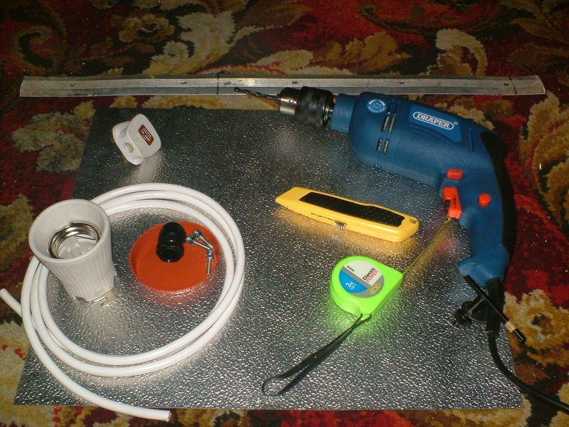
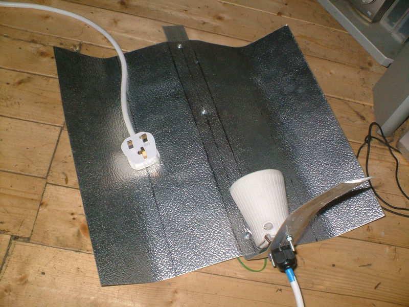
So back to the subject at hand, here is a pic of what you will need for the reflector(except the IEC connections remember!!)

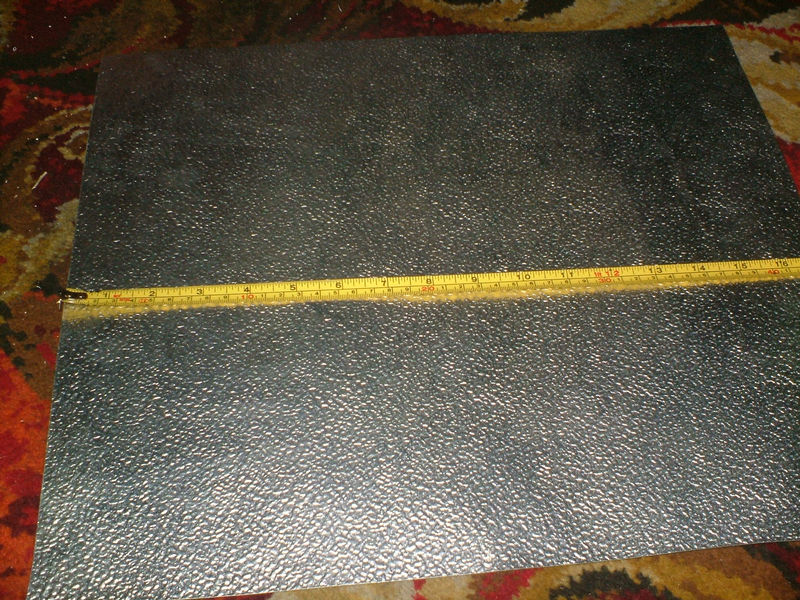
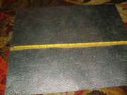
Shown here is the specular aluminium sheet, which I have had under a couple of heavy books to flatten it, 1 x aluminium carpet gripper strip 1 x 2meter's of 3 Core electrical cable (the length of flex should be 1.5M, but i always use a bit longer to start with in case i screw up and have to start again.), 1 x Ceramic lamp holder(from low bay) 1 x Compression gland, 6 x nuts and bolts with 2 washers, and 1 Female IEC("Kettle") connection (if the reflector is for the low bay conversion!). The tools required are a drill with 5mm and 20mm metal cutting bits,a Stanley knife(I believe you guys across the pond call it a "Box cutter", and a tape measure.
1st up you ned to measure the sheet of specular aluminium and mark a line down the center
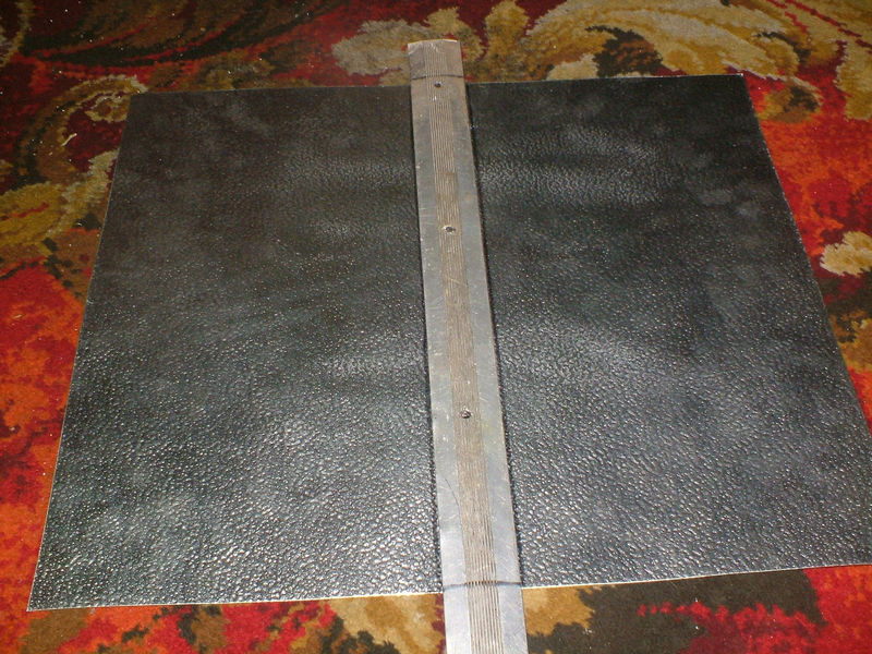
Now you take the aluminium carpet gripper, and lay it out over the centre of the sheet, lining the pre-drilled holes up with the line you marked,you want to leave about 1-2cm overhang from one end and leave the other end in tact for time being, mark the lines on the gripper where the front and rear ends of the reflector will be, and mark the edges of the gripper onto the sheet like this

now use the marker to mark where the bolts will go, using the pre drilled holes in the strip as a template. Now take the drill and fit the 5mm metalwork bit and make your holes in the sheet of aluminium.
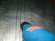
use a small file to remove any burrs and then use the nuts and bolts to fit the gripper strip to the sheet.if you have them, use shorter bolts than I did...i didn't wanna spend the 69pence when these would do the job just as well but not as aesthetically pleasing, and likewise the reason i didn't buy a brand new gripper strip when I had a load of old ones in the shed lol.
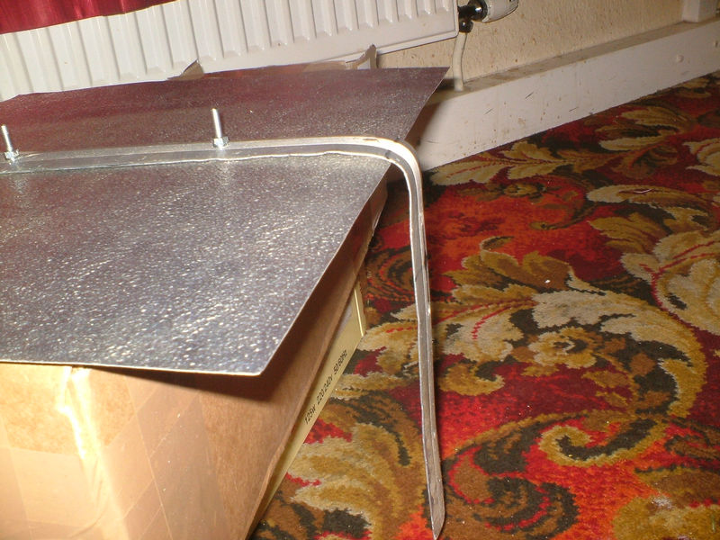
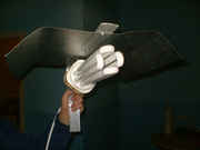
Now you are ready to bend the gripper strip to around 90 degrees to form the backing for the lamp holder...and your reflector is now starting to take shape isn't it

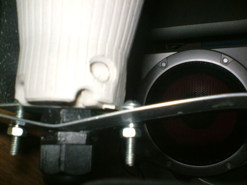
now you will need to make the holes for the bolts which will secure the ceramic lamp holder to the strip, and the big hole for the compression gland, now I did it like this
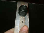
with the bolts going above and below the compression gland, but you may find it better to put the compression gland below the bottom fixing hole so that you don't have to fix the ceramic lamp colder directly to the compression gland ad bend the strip like this, if you do it with the gland below the lower fixing hole, the lamp holder will be flush against the strip with maybe 2 inches of cable running down the inside until it goes out of the compression gland...the way I did it is secure enough, but I had already started screwing it on before I realized the flaw in the design and would have had to start again with another strip( which was never gonna happen with this lazy bastard hahaha) because of the fixing holes and needing the lamp close to the sheet metal! now lets just go back a step...to just before you bolt the lamp holder on..., you 1st have to feed the end of the cable through the compression nut from the outside and tighten it up like with the ballast, and fit the ends to the contacts by tightening the brass screws up., now you can fit the lamp holder to the strip.
Now then... , if its going to be for this Low Bay - to growlight conversion, then you need to fit the female IEC ("Kettle") connection in the same way as with the male part on the ballast. If however it is going to be for an Envirolight or other CFL growing light then simply put a normal 3 pin(or whatever plug you use in your country) on the end of the cable and you are almost good to go (and grow) You should now cut the excess off the grip strip leaving only 1-2 inches maximum below the lamp holder and compression nut(Ill be doing it with mine as soon as I get a new hacksaw blade!), or alternatively, you could bend the strip double prior to drilling it out and fitting the lamp holder and compression nut to make it a bit more sturdy although this isn't really necessary. once you have done this, all that remains is to mark where you want to bend it, and then bend it...there are a lot of ways you can go about this without a press brake...the method on the floor with a piece of wood on top of it and one below, with you kneeling on the top one and using the other to bend the metal upward, or a variation on that, sandwiching the metal between 2 sheets of ply in a vice and using another to bend it towards you or away from you......me, i just did it by hand very carefully and i think i did ok. an addition will be a "V" shaped strip up the centre flat part above the bulb to make almost a dual parabola...mine is pretty angular but if you work at it you can get it rounded...I didn't wanna over do it and mess it up.
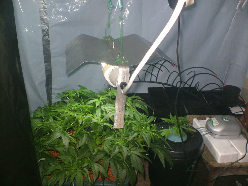
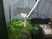
Here it is with a plug for an envirolight

and there it is in use with the envirolight in it.
so there you go everyone...a nice tidy looking remote ballast growlight and or envirolight reflector. Ill get a picture of the ballast in use and take some pics of the other reflector and both together and working when I make it to show you it with the IEC connections.
I hope this helps someone to either save some money, or make using that low bay that they have a whole lot easier, because low bays weigh quite a bit and are a real PITA to hang/adjust the height, plus with a low bay in its normal state you cant mount the ballast outside the room, which in turn makes ur temps higher. i know how tempting they are when you look at the price when compared with a ready made growlight... Its up to you if you use the existing bulb...no reason not to unless its way old...
i think the very best thing about this conversion is that except for the compression glands,3 core and IEC Fittings, (which were about 5 pounds altogether), and the strip connector,nuts and bolts and the carpet gripper strip(which i already had in the shed) which are only small bits and pieces,the whole thing is pretty much made from the original low bay housing...If you want to/can be arsed(coz I couldn't due to terminal laziness ) you could cut the backing strip (which is the backbone of the reflector )from the discarded reflector part of the low ba housing that you cut off, making it even more recycled than it already is now...and remember, my carpet gripper strip was an old used one so is still recycled lol.... and maybe recycling materials like this will cancel out the addition to the hole in the Ozone layer from all our lights lol, just trying to do my bit.
well guys n girls, that took a longtime to type...about 10 times longer than it took to put the damned thing together but hey ho,lol.
ill be off now, but I will as promised come back and ,make the required alterations/additions/improvements to the thread as soon as i have the pictures.
Any questions comments welcome.
Finally I would like to say MAKE SURE ANY ELCTRICAL CONNECTIONS YOU DO ARE TIDY AND SECURE, NOTHING LOOSE OR STRAY electricity isn't something to be fucked around with...so if you decide to undertake anything electrical, even something as simple as this is, BE CAREFUL.
so, I'm off, another great instructional from Budget and Scraper DIY and fabrications Ltd
catch you all later,
Be lucky now,
Harry
EDIT Forgot to add the pic of the reflector with the enviro in it being used....
Thought this was a good read so I cleaned up a shit ton of spelling errors to make it a little easier on the eyes and then I archived it over here. If a mod would like to organize/Spell/Grammar fix some more feel free 
Hope you enjoy! 
Quote:
Source URL: http://www.icmag.com/ic/showpost.php?p=252602&postcount=1
Edited by GROWEED (05/23/08 01:04 AM)
| |
|
|
|
|